
Bidirectionele logic level convertor
Doel: omzetten van signalen van 3.3V naar 5v en van 5V terug naar 3.3V.
In een aantal gevallen zullen actuatoren en sensoren nog werken met 5V logica. Om deze te kunnen aansluiten op onze BBiot die op 3.3V werkt moeten we deze module er tussen zetten.


DESCRIPTION
The Logic Level Converter 8-Ch Bi-Directional Module allows you to connect almost any 2 different voltage logic circuits together like 3.3V and 5V.
PACKAGE INCLUDES:
- Logic Level Converter 8-Ch Bi-Directional Module
- Qty 2 – 10-pin male header strip
KEY FEATURES OF LOGIC LEVEL CONVERTER 8-CH BI-DIRECTIONAL MODULE:
- 8 channels can convert up to 8 logic signals
- Can convert between 1.8V, 2.8V, 3.3V and 5V logic circuits
- Bi-directional so can work with bi-directional buses such as I2C
- Utilizes N-Ch MOSFET transistors for level translation
- Headers on 0.45″ centers (see our Module Assembly notes down below)
This module is typically used to connect 3.3V and 5V logic signals together, but it is compatible with many different logic voltages including 1.8V and 2.8V as found in some of the newer devices. It will also work with most oddball voltages if you have some special conversion requirement
There are 8 bi-directional channels which is especially useful for buses such as I2C that pass data in both directions or bi-directional data buses. It can also be used for unidirectional signals like TTL serial communications as well as standard logic signals.
The circuit makes use of N-Channel MOSFET transistors and some pull-up resistors to take care of the voltage translation.
Module Operation
To use the module, you hook up the two voltages that you want to convert between to the LV (low Voltage) and HV (High Voltage) inputs. The higher voltage is always connected to the HV side.
If using with an Arduino, you would typically connect the 3.3V output of the Arduino to the Low Voltage (LV) input and the 5V output of the Arduino to the High Voltage (HV) input.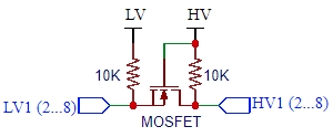
There are two grounds on the board as well. These aren’t used by the circuit on the board, but can be used to pass a ground connection along with the data between the systems if it is needed.
You then hook-up the lower voltage logic signals to the LV1-LV8 pins and the higher voltage logic signals to the corresponding HV1-HV8 pins (LV1 connects to HV1, etc) and you are set to go. There is no direction control required for the bi-directional functionality.
MOSFET translators like this are best used for slow to moderate speed signals. They will typically work fine at I2C 400kHz type speeds, but may or may not work reliably with high speed signals like SPI.
Module Assembly
The module comes with 2 strips of male headers. These can be soldered on either side of the board or you can attach wires directly to the board depending on what your application requires.
An important note: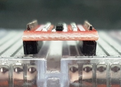
The two rows of headers are on about 0.45″ centers rather than being on a standard 0.4″ or 0.5″ spacing. It can be made to work with breadboards or perf boards, but the headers will need to be soldered into the module at a slight angle.
This is most easily accomplished by putting the headers into a solderless breadboard and then pressing on the module before soldering. The picture shows the angle you end up with on the headers.
Module Connections
The board has the following I/O connections:
- HV = High voltage. Must be higher voltage than LV. Typically tied to 5V
- LV = Low voltage. Must be lower voltage than HV. Typically tied to 3.3V
- GND = Ground (x2). Can be used to pass a ground between the two different voltage circuits
- HV1 / LV1 = Channel 1
- HV2 / LV2 = Channel 2
- HV3 / LV3 = Channel 3
- HV4 / LV4 = Channel 4
- HV5 / LV5 = Channel 5
- HV6 / LV6 = Channel 6
- HV7 / LV7 = Channel 7
- HV8 / LV8 = Channel 8